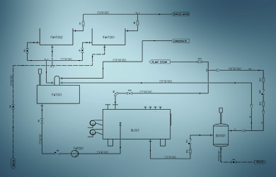
A piping & instrumentation diagram is a highly important document used for process plant design and contains a wide-range of detailed information
The piping & instrumentation diagram (P&ID) is a highly important document for process plant design. Despite its simplicity, it contains a wide-range of detailed design information. But what exactly is behind a P&ID?
What is a Piping & Instrumentation Diagram?
Piping & instrumentation diagrams (P&IDs) are used to schematically represent a design, and are usually created before any physical equipment design or layout takes place. All of the equipment and instrumentation required for a process is depicted using symbols, and any interconnecting pipework is represented using simple lines. P&IDs contain a considerable amount of detailed information about the design such as equipment tags, line labels, bore sizes, quantities and connectivity. But how can so much information be accommodated within such a simple diagram?
Creating P&IDs – Without Errors
One of the biggest advantages of modern P&ID software packages is their ability to automatically check the entire design for consistency and errors during the drafting process. The latest P&ID systems generate a detailed list of problem areas and highlight them on the P&ID. This allows the designer to quickly and easily make corrections and prevent the issues from affecting subsequent project phases.
A modern P&ID system
One software package that stands out due to its intelligence and sheer flexibility is CAD Schroer’s M4 P&ID FX. This system is highly affordable and has all the functionality you need to quickly and accurately create intelligent P&IDs. Its extensive attribute capabilities and customisable parts list generation set it apart from other packages on the market, which often cost a lot more but do a lot less. It is also extremely easy to use, and is supported with video tutorials to help you get started. P&IDs are the basis for process design. They can be quickly and accurately created using modern P&ID software to ensure a high quality design.
>> What is a piping & instrumentation diagram and how can I quickly create one without errors?
https://www.cad-schroer.com/news/articles/piping-instrumentation-diagram-what-is-it-practical-advantages-and-tips/
